VFX optimisation in midcore games: Commonly overlooked techniques and advanced methods

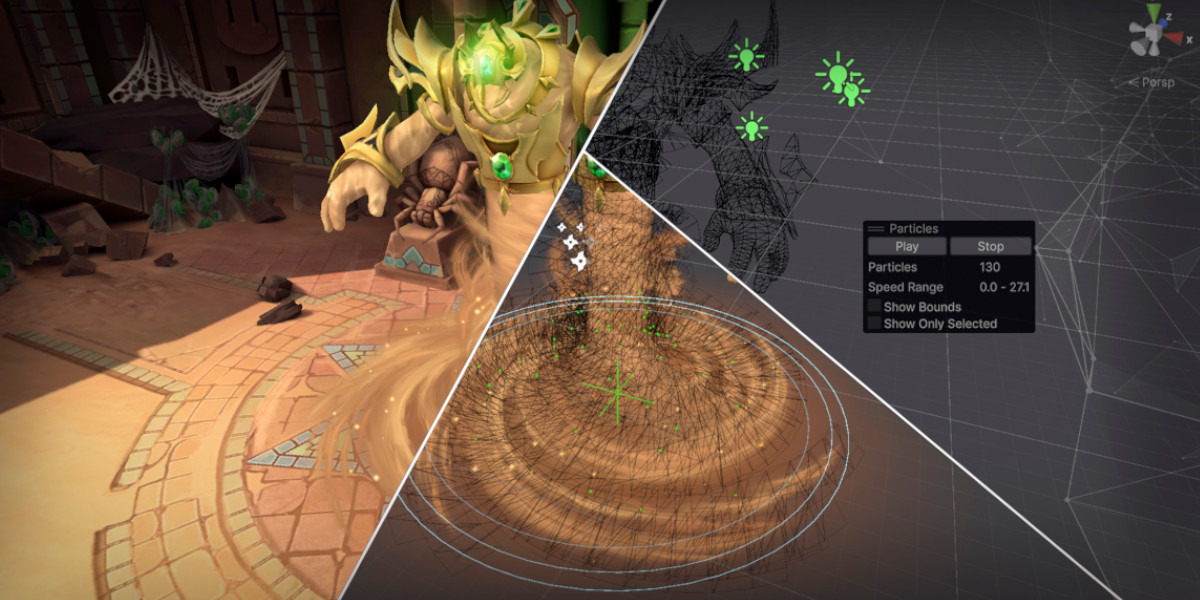
- Build VFX with optimisation in mind from the outset to avoid performance issues later in production.
- VFX budgets should be based on how many effects can appear simultaneously, not just the quality of individual effects.
Stanislav Stabrov is lead VFX at Azur Games.
VFX optimisation in a midcore game: Commonly overlooked basics and advanced techniques
Kingdom Clash is a midcore game built around battles between two large armies of fantasy units and heroes, each with their own classes, abilities, and visual effects.
Spectacle and visual quality are obviously important here. But when developers focus too heavily on visuals and production speed, complex effects are often built with little thought given to optimisation. In extreme cases, this can even put a release at risk.
In reality, effects can be designed from the start to look good, run reliably, and avoid putting excessive load on the device. Yet basic optimisation principles are often ignored, whether because of limited experience, lack of attention, or simple production pressure. The result is heavier effects and noticeable frame-rate drops.
Below, we’ll go through several areas worth considering while building the effects themselves, before moving on to shader optimisation.
Everything covered here comes from hands-on experience, real production work, and mistakes made on live projects.
We’ll start with the basics - which are surprisingly often overlooked - and then move on to more advanced techniques.
Step 1. Identify simple effects and bake their particle systems into textures
Let’s say we have a projectile impact effect that occupies a relatively small area on screen. Visually, we can divide it into two main parts: a flash at the centre and a wave expanding outward.
Both the flash and the wave may consist of multiple particle systems: sparks, shockwaves, rays, debris, fire bursts, smoke particles, and so on. But when many small, identical effects appear on screen at the same time, all those individual details tend to merge into small but recognisable silhouettes.
This suggests that the independent motion of every tiny element is not always that important. What matters more is how the effect reads in the frame at the moment it triggers. The movement of individual details can sometimes be sacrificed in exchange for better performance.
The movement of individual details can sometimes be sacrificed in exchange for better performance.
The simplest - and perhaps most brute-force - approach is to capture individual parts of the explosion, or even the entire explosion, and bake the result into a texture. Instead of spawning a flash and a whole collection of particle systems for the expanding wave, we can then render the effect with just two particles: one for the flash and one for the wave.
In the type of scenario we’re discussing, where small effects appear frequently and in large numbers, only someone deliberately inspecting them is likely to notice the difference.
Let’s look at a projectile impact as an example. We can divide its visual into a flash and an expanding wave, then optimise it as follows:
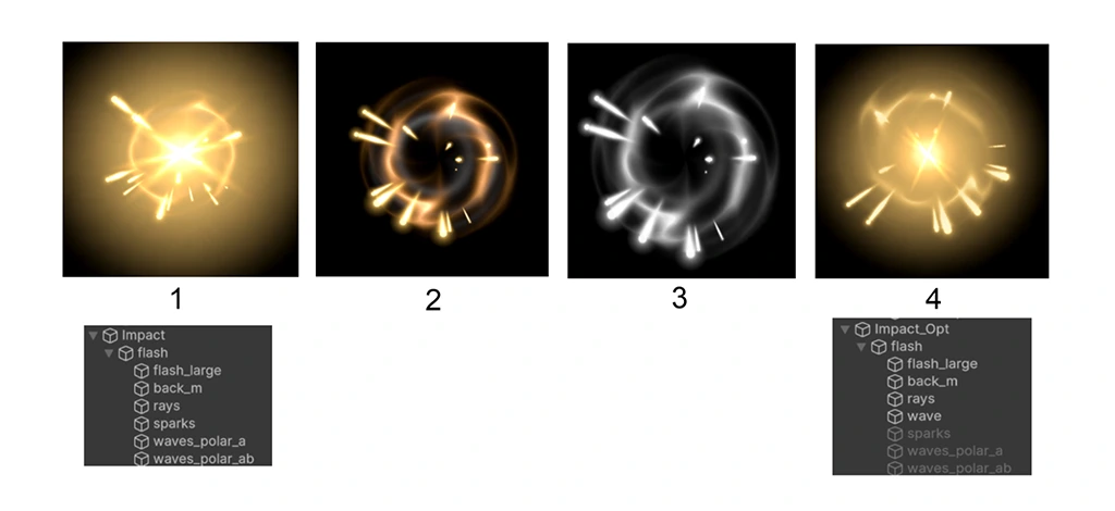
1 - A poorly optimised projectile impact. The flash and wave use multiple particle systems, with approximately 30 particles in total.
2 - Disable the particle systems responsible for the flash, leaving only the wave.
3 - Position the wave in front of the isometric camera and capture it as a texture.
4 - Disable the original wave particle systems and replace them with a single particle using the captured texture. The effect loses some internal motion but keeps its overall silhouette. The
particle count drops to approximately 10.
We can then apply the same process to the remaining flash systems, eventually reducing the entire effect to just two particles.
From the gameplay camera, the difference looks roughly like this:
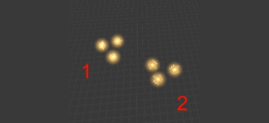
1 - Original effects
2 - Optimised effects
The reduction is substantial: from 30 particles to 2. This becomes even more significant in the situations where this method works best. If ten copies of the effect are triggered at once, the optimisation reduces the total from 300 particles to 20. At that scale, the performance gain becomes much more noticeable.
However, this simple method has clear limitations. It works primarily because of how player attention is distributed. Effects optimised this way should generally be small, fast, frequent, and visually secondary. In other words, their execution should not draw close attention. Ideally, the player should only register the silhouette for a brief moment rather than have time to inspect its internal detail. The larger, slower, and less frequent an effect is, the more individual layers you will need to preserve.
This leads to the first general rule for working with particles: whenever possible, put detail into the texture rather than creating it through particle count.
This leads to the first general rule for working with particles: whenever possible, put detail into the texture rather than creating it through particle count. It is often better to create one complex texture and spawn several copies of it than to recreate the same visual using a large number of simple particles.
At the same time, particle-count limits, like most optimisation limits, depend heavily on the project. The most important factor is how many copies of each effect may appear simultaneously. If the scene contains a duel between two characters who cast a spell once per minute, visual impact may matter far more than optimisation. There may be little else on screen besides two character models and their effects, so using hundreds of particles may be perfectly acceptable.
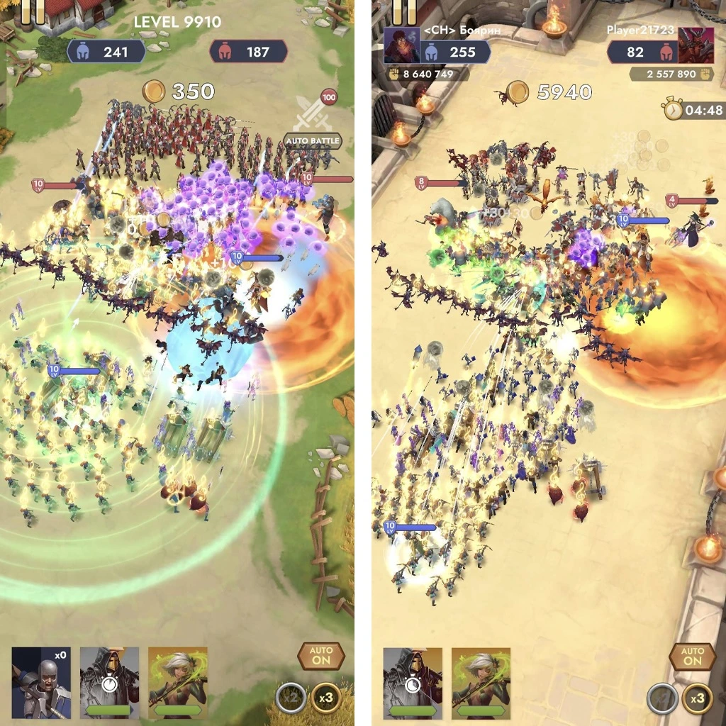
In Kingdom Clash, however, two large armies containing dozens or even hundreds of units can fight at the same time, with each unit generating its own effects. If a single effect uses 100 particles and 200 units can trigger it, the total quickly becomes unreasonable. That is why our limits can be as low as 3–10 particles per effect.
Step 2. Reduce particle count by increasing particle size
A common mistake is filling a volume of smoke with a large number of small particles when the same cloud could be represented by far fewer, larger particles.
The same principle often applies to sparks. You usually don’t need a huge number of them to make an effect look good. The player is unlikely to care whether 100 sparks were emitted or 30 - but the device will.
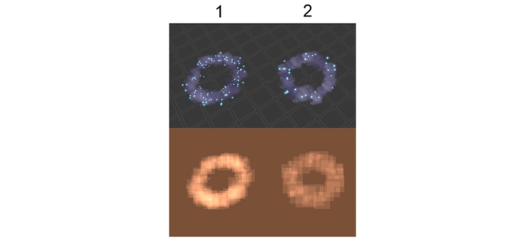
1 - Poorly optimised effect. The smoke cloud is filled with many small smoke particles, and the number of sparks is excessive. Total particle count: 200.
2 - Optimised effect. The result looks slightly simpler, but very little of the essential visual has been lost. The smoke cloud is formed using fewer, larger particles, while sparks are used only as an accent, with just enough of them to spread evenly through the effect. Total particle count: 50.
It is worth remembering that increasing particle size also increases overdraw. In most cases, however, this additional cost is offset by the much lower overall number of large particles in the effect.
Step 3. Replace particles with a mesh and shader
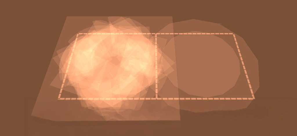
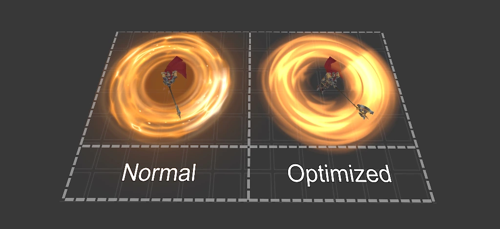
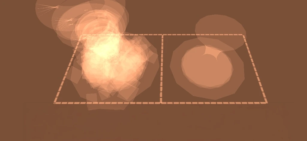
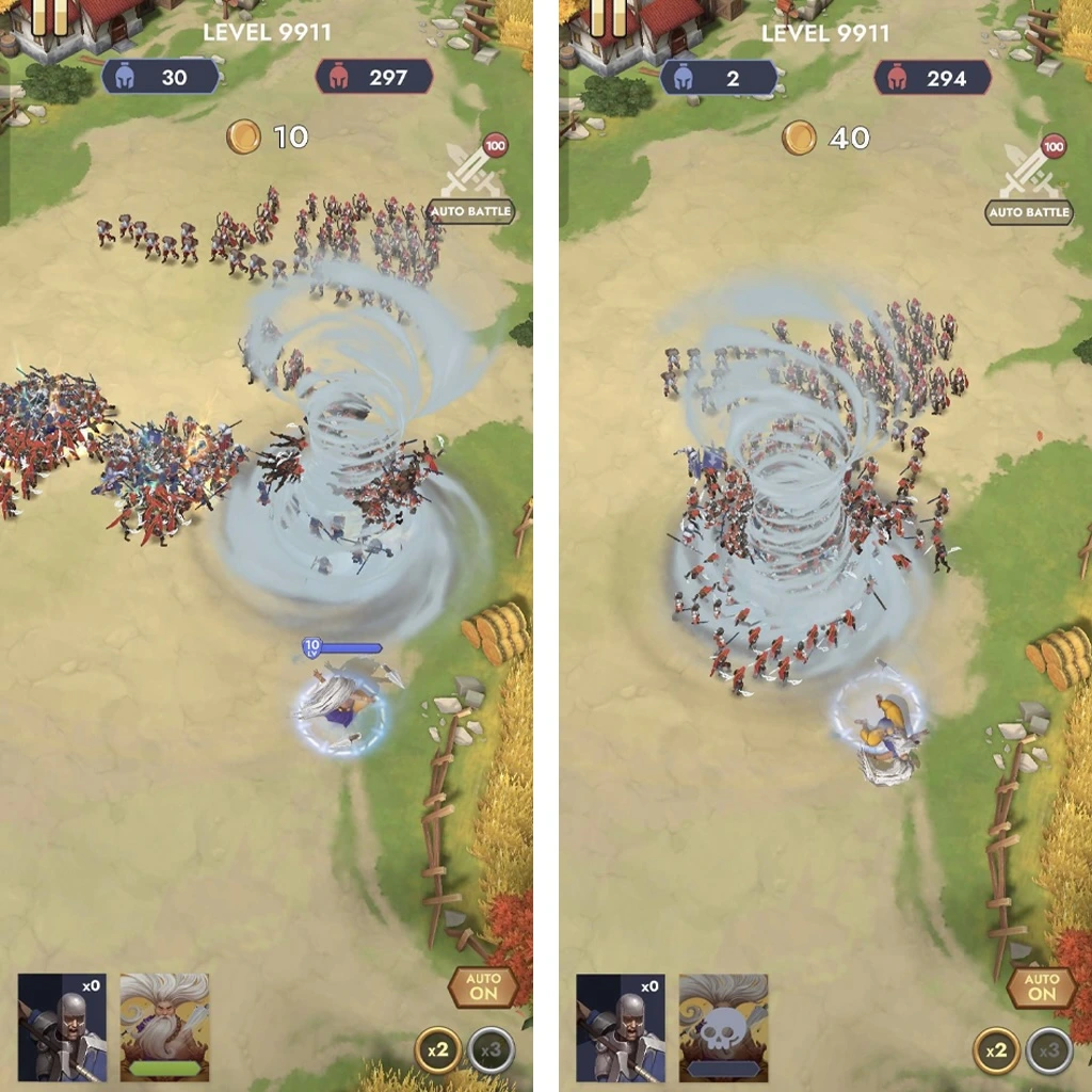
If part of an effect is built from many particles moving in a mostly linear or predictable way, that entire volume can sometimes be replaced with a single mesh carrying an animated noise texture. With a well-chosen texture and shader, the result may even look cleaner than the particle-based version.
Here are several examples before and after optimisation:
Step 4. Reduce overdraw
Reducing particle count, especially the number of large particles, already helps reduce overdraw. But overdraw deserves direct attention of its own, because it can become a bottleneck even when the total number of particles on screen appears relatively low.
The renderer processes particle coverage pixel by pixel. Since this is an area calculation, doubling the width and height of a quad particle increases its screen-space area - and therefore the number of affected pixels - by four times.
The most basic way to prevent overdraw problems is to prepare effect textures properly.
The most basic way to prevent overdraw problems is to prepare effect textures properly.
As discussed above, the renderer processes the full area covered by each particle. That means we should use that texture area as efficiently as possible.
When creating a texture, try to make the visible image occupy as much of the texture as practical, without leaving large amounts of transparent, unused space. The entire textured quad is still rendered. By reducing empty space around the visible part, we can sometimes reduce pixel workload significantly.
In the examples below, the red areas show unused space. The player cannot see these areas, but the renderer still processes them.
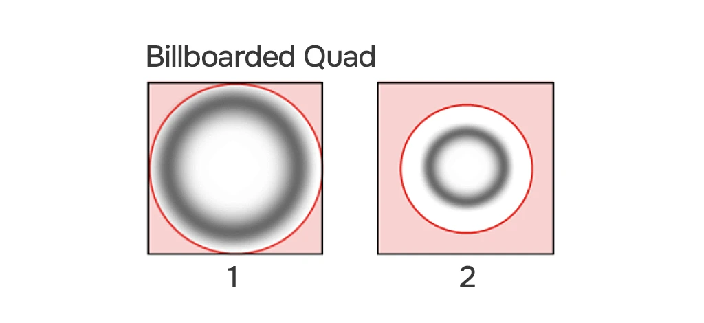
The first texture is prepared correctly: only the corners of the quad are unused.
The second texture is prepared poorly: more than half of the quad’s area is rendered without contributing anything visible.
To reduce unused area even further, we can modify the mesh that carries the texture.
If the texture has a relatively simple silhouette, the mesh can be shaped to follow that silhouette more closely.
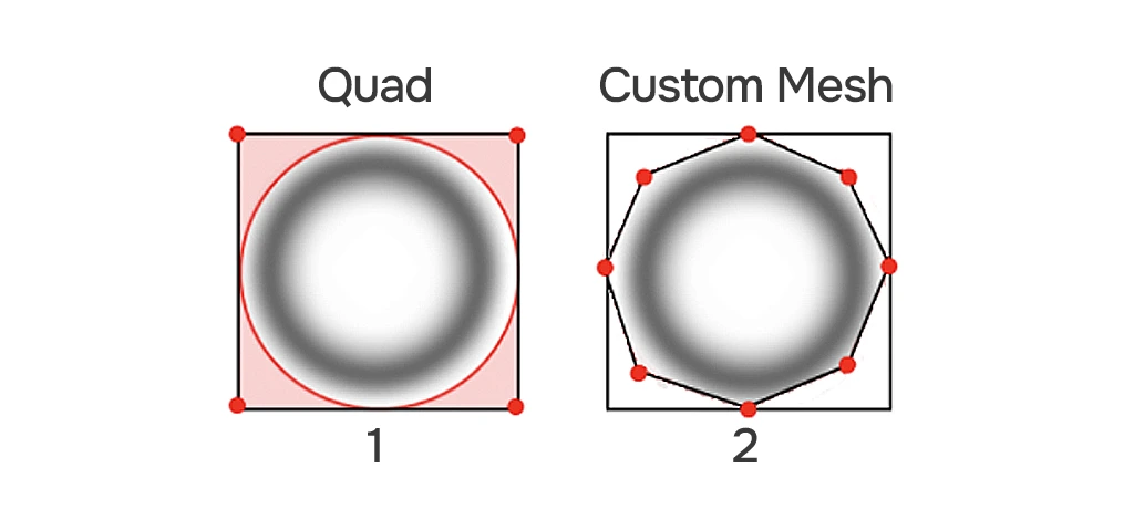
The first image uses a standard quad billboard, leaving small areas of unused coverage.
The second uses a custom mesh with additional vertices that cut away unused surface area.
A more complex mesh is appropriate primarily for relatively large particles, such as flashes, shockwaves, or vortexes - cases where reducing pixel coverage produces a meaningful gain. For a cloud of tiny particles, there is little point in adding vertices to save only a few dozen pixels on screen.
This technique has no visible impact on the quality of the effect, but it can make a significant difference to performance.
Step 5. Optimise particle system modules
Particle System modules also have different performance costs. Enabling many of them without considering whether they are actually needed can create unnecessary overhead. The first recommendation is therefore simple: enable only the modules required to achieve the intended visual. When choosing between two modules that can produce a similar result, prefer the simpler one when the visual difference is negligible.
Modules that should not be enabled repeatedly without a clear reason include: Collision, Noise, and Trails. In some cases, their behaviour can be approximated using simpler modules.
For example:
Replacing Collision: Instead of using the Collision module, particles can sometimes be stopped abruptly with Limit Velocity over Lifetime. The timing can be adjusted so that particles lose their velocity when they visually reach the ground plane, creating the impression of a collision without running actual particle collision calculations.
Instead of using the Collision module, particles can sometimes be stopped abruptly with Limit Velocity over Lifetime.
Replacing Noise: Pseudo-random movement can sometimes be created by carefully configuring curves in Velocity over Lifetime. With the right settings, the result can appear random enough without using the Noise module.
It is also worth avoiding an excessive number of highly complex curves in Particle System settings when simpler curves can produce a comparable result.
Step 6. Reduce draw calls
Another important optimisation direction is reducing draw calls.
In general, fewer draw calls mean less work for the rendering pipeline. Compatible particle systems that use the same material may be batched, reducing the number of draw calls. One of the most common ways to support this is to pack effect textures into a texture atlas. The atlas can be used as a shared material across many effects, giving the system more opportunities to batch compatible geometry and reduce material switches.
Another important optimisation direction is reducing draw calls.
It also helps to design a flexible shared VFX shader. The shader can expose the parameters most commonly changed between effects, such as brightness or emissive intensity, panning speed, alpha-channel handling, and so on. These values can then be passed through the Particle System’s Custom Data module.
This means that making one particle brighter or changing the speed of its scrolling noise does not require creating a new texture or a separate material. Instead, the relevant parameter can be changed directly in the particle system. As a result, we reduce the number of unnecessary material variants in the scene.
Step 7. Optimise VFX shaders
Like every rendered object in a scene, particles use shaders. These shaders can also be inefficient or simply too expensive for mobile hardware.
In the section on overdraw, we mentioned per-pixel calculations - the shader code executed for every fragment covered by a rendered object. When discussing shader optimisation here, we are primarily talking about reducing the cost of fragment shader code.
Historically, GPUs have been highly efficient at basic arithmetic operations such as multiplication, addition, and subtraction. More complex operations, such as exponentiation and trigonometric functions, have generally been much more expensive.
As a result, shader logic should generally rely on straightforward arithmetic whenever practical: addition (+), multiplication (*), subtraction (-), division (/), and functions built around these operations, such as lerp().
Functions such as saturate(), which clamps a value to the 0–1 range, and abs(), which returns the absolute value, are also typically inexpensive.
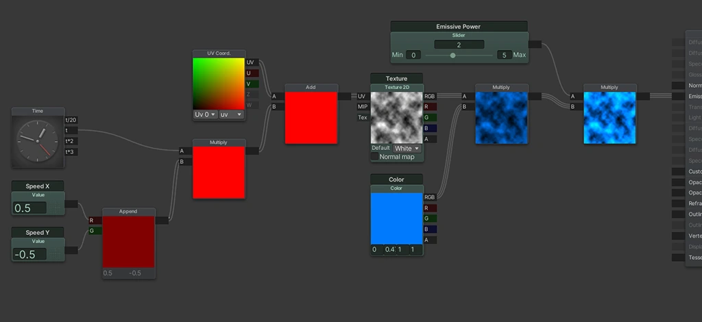
More expensive operations may include: sine – sin(), cosine – cos(), two-argument arctangent – atan2(), and trigonometric operations in general. Exponentiation (pow()) may also be very costly. These functions should not be treated as universally forbidden, but they should be used intentionally rather than by default.
GrabPass { } should also generally be avoided in mobile development.
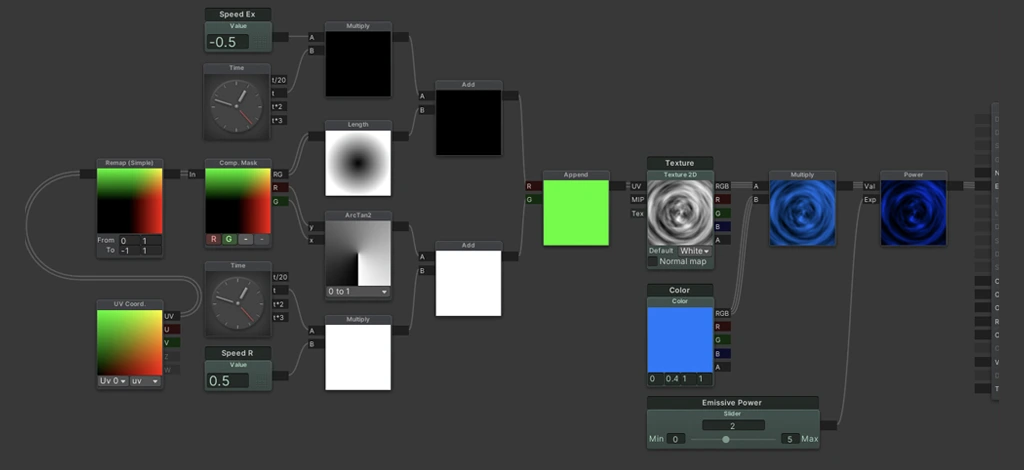
These considerations are guidelines rather than absolute bans. If we build a complex shader that relies heavily on trigonometric operations - for example, one using polar coordinates - we can still use it. But we need to remember that its fragment calculations are relatively expensive. As a result, particles using that shader should ideally be rare and occupy limited screen space.
Conversely, if we create a basic shader using one texture and a few arithmetic operations, it can be reused much more freely across many effects.
In some cases, calculations can be moved out of the fragment shader into the vertex shader. This works for operations that do not require per-pixel precision and can be interpolated across the mesh without visible loss of quality.
For example:
v2f vert (appdata v)
v2f o;
o.vertex = UnityObjectToClipPos(v.vertex);
o.uv.xy = v.uv.xy;
o.vertexColor = v.vertexColor;
return o;
float4 frag (v2f i) : SV_Target
float2 uv = float2(_SpeedX, _SpeedY) * _Time.y + i.uv.xy;
uv = TRANSFORM_TEX(uv, _MainTex);
float4 col = tex2D(_MainTex, uv);
col.rgb = col.rgb * i.vertexColor.rgb * _EmissivePower;
return col;
(unoptimised panning shader)
1. Suppose we want to build a panning shader in which a noise texture scrolls across a mesh.
To create this movement, we need to offset the UV coordinates uniformly across the entire rendered surface. Because the same offset is applied everywhere, it does not need to be recalculated independently for every fragment. Instead, we can calculate the offset at the quad’s vertices and let the GPU interpolate the values between them.
The UV-offset logic is moved into the vertex shader, while the fragment shader receives the already interpolated result. For a quad, this means the UV offset is calculated only four times, regardless of how many pixels the effect covers on screen.
v2f vert (appdata v)
v2f o;
o.vertex = UnityObjectToClipPos(v.vertex);
o.uv.xy = v.uv.xy;
o.uv.xy = float2(_SpeedX, _SpeedY) * _Time.y + o.uv.xy;
o.vertexColor = v.vertexColor;
return o;
float4 frag (v2f i) : SV_Target
float2 uv = TRANSFORM_TEX(i.uv.xy, _MainTex);
float4 col = tex2D(_MainTex, uv);
col.rgb = col.rgb * i.vertexColor.rgb * _EmissivePower;
return col;
(optimisation: moving UV panning into the vertex shader)
2. If we want to make the entire image uniformly brighter, we multiply it by a value greater than one.
If the image is already being multiplied by a colour value, such as the particle’s vertex colour, we can combine the brightness multiplier with that colour in the vertex shader. This removes one multiplication from the fragment shader.
v2f vert (appdata v)
v2f o;
o.vertex = UnityObjectToClipPos(v.vertex);
o.uv.xy = v.uv.xy;
o.uv.xy = float2(_SpeedX, _SpeedY) * _Time.y + o.uv.xy;
o.vertexColor = v.vertexColor;
o.vertexColor.rgb = o.vertexColor.rgb * _EmissivePower;
return o;
float4 frag (v2f i) : SV_Target
float2 uv = TRANSFORM_TEX(i.uv.xy, _MainTex);
float4 col = tex2D(_MainTex, uv);
col.rgb = col.rgb * i.vertexColor.rgb;
return col;
(optimisation: moving the brightness multiplier into the vertex shader)
3. The Transform macro, which applies texture tiling and offset, can also be moved into the vertex shader. This saves another two operations — multiplication and addition in the fragment shader.
v2f vert (appdata v)
v2f o;
o.vertex = UnityObjectToClipPos(v.vertex);
o.uv.xy = v.uv.xy;
o.uv.xy = float2(_SpeedX, _SpeedY) * _Time.y + o.uv.xy;
o.uv.xy = TRANSFORM_TEX(o.uv.xy, _MainTex);
o.vertexColor = v.vertexColor;
o.vertexColor.rgb = o.vertexColor.rgb * _EmissivePower;
return o;
float4 frag (v2f i) : SV_Target
float4 col = tex2D(_MainTex, i.uv.xy);
col.rgb = col.rgb * i.vertexColor.rgb;
return col;
(optimisation: moving texture tiling and offset into the vertex shader. The fragment shader is left with only a texture sample and a colour multiplication)
A useful intuitive rule is this: a calculation can often be moved from the fragment shader to the vertex shader when it applies uniformly to the entire rendered image - for example, if we’re moving the whole texture, or brightening the entire image. But if we want to brighten only the centre while leaving the edges unchanged, we will generally need per-fragment calculations.
A useful intuitive rule is this: a calculation can often be moved from the fragment shader to the vertex shader when it applies uniformly to the entire rendered image.
However, the answer also depends on the mesh used by the shader. The denser the mesh, the more detailed the calculations we can perform in the vertex shader, because the vertices effectively become additional interpolation points.
A Fresnel effect is a good example of a less obvious trade-off. We may be able to calculate it in the vertex shader, but its smoothness will then depend on mesh density. To preserve a smoother result, we would need a more detailed mesh. At some point, it may be better to keep the Fresnel calculation in the fragment shader rather than increase mesh complexity.
In conclusion
Creating effects that are both attractive and efficient is not especially difficult. Many of the most important decisions only need to be made once, near the beginning of production - for example, preparing a shared texture atlas or establishing good standards for effect textures.
The workflow can also be simplified significantly by creating a set of reference-quality, optimised effects at the start of the project and using copies of them as the foundation for new work.
New effects will then inherit at least part of the clean, efficient setup of their originals.
If all these methods and recommendations are applied consistently, modern devices should have very little reason to struggle with VFX performance.
Companies

People
